Why Is My Arduino Reading 1 Volt on Pin 0
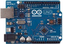
Arduino hardware
Arduino is an open-source electronics platform based on easy-to-use hardware and software. Information technology'due south intended for anyone making interactive projects. Arduino senses the environment by receiving inputs from many sensors, and affects its surroundings by controlling lights, motors, and other actuators. You tin tell your Arduino what to do past writing code in the Arduino programming language and using the Arduino development environment.
Source: http://www.arduino.cc/
Introduction: What Arduino is and why you'd want to utilise it.
Installation: Step-by-step instructions for setting upwards the Arduino software and connecting it to an Arduino Uno, Mega2560, Duemilanove, Mega, or Diecimila.
Windows
Mac OS 10
Linux (on the playground wiki)
Environment: Description of the Arduino development environment and how to alter the default linguistic communication.
Libraries: Using and installing Arduino libraries.
Troubleshooting: Advice on what to exercise if things don't work.
The Arduino Uno is a microcontroller board based on the ATmega328 (datasheet). It has 14 digital input/output pins (of which half-dozen tin be used equally PWM outputs), half-dozen analog inputs, a xvi MHz ceramic resonator, a USB connectedness, a power jack, an ICSP header, and a reset button. Information technology contains everything needed to support the microcontroller; only connect it to a computer with a USB cable or ability information technology with a AC-to-DC adapter or battery to go started.
Arduino Uno Specifications
Microcontroller – ATmega328;
Operating Voltage – 5V;
Input Voltage (recommended) – 7-12V;
Input Voltage (limits) – 6-20V;
Digital I/O Pins – 14 (of which half-dozen provide PWM output);
Analog Input Pins – 6;
DC Electric current per I/O Pin – twoscore mA
DC Current for 3.3V Pivot – fifty mA;
Flash Memory – 32 KB (ATmega328) of which 0.five KB used past bootloader;
SRAM – two KB (ATmega328);
EEPROM – 1 KB (ATmega328);
Clock Speed – 16 MHz;
Interfacing with hardware
Collection of data and software resources for interfacing Arduino cards with a wide range of hardware devices at www.arduino.cc
Programming Language reference
Online language reference for Arduino programming, using the gratis IDE development environs.
Programming
The Arduino Uno tin can be programmed with the Arduino software (download). Select "Arduino Uno from the Tools > Board carte (according to the microcontroller on your board). For details, encounter the reference and tutorials.
The ATmega328 on the Arduino Uno comes preburned with a bootloader that allows you to upload new lawmaking to it without the use of an external hardware programmer.
Retentivity
The ATmega328 has 32 KB (with 0.5 KB used for the bootloader). It also has ii KB of SRAM and 1 KB of EEPROM (which tin can exist read and written with the EEPROM library).
Input and Output
Each of the 14 digital pins on the Uno tin can be used every bit an input or output, using pinMode(), digitalWrite(), and digitalRead() functions. They operate at 5 volts. Each pin can provide or receive a maximum of 40 mA and has an internal pull-up resistor (disconnected by default) of 20-50 kOhms. In addition, some pins accept specialized functions:
Serial: 0 (RX) and i (TX). Used to receive (RX) and transmit (TX) TTL serial information. These pins are connected to the corresponding pins of the ATmega8U2 USB-to-TTL Serial chip.
External Interrupts: ii and three. These pins can be configured to trigger an interrupt on a low value, a rising or falling border, or a change in value. See the attachInterrupt() role for details.
PWM: 3, v, 6, 9, x, and 11. Provide 8-bit PWM output with the analogWrite() function.
SPI: 10 (SS), xi (MOSI), 12 (MISO), thirteen (SCK). These pins back up SPI advice using the SPI library.
LED: 13. At that place is a built-in LED continued to digital pin 13. When the pivot is HIGH value, the LED is on, when the pin is Depression, it's off.
The Uno has 6 analog inputs, labeled A0 through A5, each of which provide x bits of resolution (i.e. 1024 dissimilar values). By default they mensurate from ground to 5 volts, though is it possible to change the upper cease of their range using the AREF pin and the analogReference() part. Additionally, some pins take specialized functionality:
TWI: A4 or SDA pin and A5 or SCL pin. Support TWI advice using the Wire library.
There are a couple of other pins on the board:
AREF. Reference voltage for the analog inputs. Used with analogReference().
Reset. Bring this line Low to reset the microcontroller. Typically used to add a reset button to shields which block the one on the board.
Communication
The Arduino Uno has a number of facilities for communicating with a computer, another Arduino, or other microcontrollers. The ATmega328 provides UART TTL (5V) serial communication, which is bachelor on digital pins 0 (RX) and 1 (TX). An ATmega16U2 on the board channels this serial communication over USB and appears as a virtual com port to software on the computer. The '16U2 firmware uses the standard USB COM drivers, and no external driver is needed. All the same, on Windows, a .inf file is required. The Arduino software includes a serial monitor which allows uncomplicated textual data to be sent to and from the Arduino lath. The RX and TX LEDs on the board will flash when data is being transmitted via the USB-to-serial bit and USB connection to the calculator (only not for serial communication on pins 0 and 1). A SoftwareSerial library allows for serial advice on any of the Uno's digital pins.
The ATmega328 also supports I2C (TWI) and SPI advice. The Arduino software includes a Wire library to simplify utilize of the I2C bus; see the documentation for details. For SPI communication, utilise the SPI library.
Power
The Arduino Uno can be powered via the USB connection or with an external power supply. The power source is selected automatically. External (non-USB) ability can come either from an Air conditioning-to-DC adapter (wall-wart) or battery. The adapter tin exist connected by plugging a 2.1mm heart-positive plug into the board's power jack. Leads from a bombardment tin exist inserted in the Gnd and Vin pivot headers of the POWER connector. The board can operate on an external supply of 6 to 20 volts. If supplied with less than 7V, even so, the 5V pin may supply less than five volts and the board may be unstable. If using more than 12V, the voltage regulator may overheat and damage the lath. The recommended range is seven to 12 volts.
The power pins are every bit follows:
VIN. The input voltage to the Arduino board when it'southward using an external power source (as opposed to five volts from the USB connection or other regulated power source). You tin supply voltage through this pin, or, if supplying voltage via the power jack, access it through this pin.
5V.This pin outputs a regulated 5V from the regulator on the board. The lath can be supplied with power either from the DC ability jack (7 - 12V), the USB connector (5V), or the VIN pivot of the board (7-12V). Supplying voltage via the 5V or three.3V pins bypasses the regulator, and tin damage your lath. We don't advise it.
3V3. A 3.three volt supply generated by the on-lath regulator. Maximum current depict is 50 mA.
GND. Ground pins.
IOREF. This pivot on the Arduino board provides the voltage reference with which the microcontroller operates. A properly configured shield can read the IOREF pin voltage and select the appropriate power source or enable voltage translators on the outputs for working with the 5V or three.3V.
Automated (Software) Reset
Rather than requiring a physical press of the reset button earlier an upload, the Arduino Uno is designed in a way that allows it to be reset past software running on a continued figurer. One of the hardware flow control lines (DTR) of the ATmega8U2/16U2 is continued to the reset line of the ATmega328 via a 100 nanofarad capacitor. When this line is asserted (taken depression), the reset line drops long enough to reset the chip. The Arduino software uses this capability to let you to upload code by simply pressing the upload button in the Arduino environment. This means that the bootloader can have a shorter timeout, as the lowering of DTR tin be well-coordinated with the start of the upload.
This setup has other implications. When the Uno is connected to either a computer running Mac Os X or Linux, it resets each time a connectedness is fabricated to it from software (via USB). For the following half-second or so, the bootloader is running on the Uno. While information technology is programmed to ignore malformed information (i.e. annihilation besides an upload of new code), it will intercept the first few bytes of data sent to the lath after a connexion is opened. If a sketch running on the board receives erstwhile configuration or other information when it first starts, make certain that the software with which it communicates waits a second afterward opening the connexion and before sending this data.
The Uno contains a trace that can be cutting to disable the car-reset. The pads on either side of the trace tin can be soldered together to re-enable it. Information technology'southward labeled "RESET-EN". You may too exist able to disable the auto-reset by connecting a 110 ohm resistor from 5V to the reset line; run into this forum thread for details.
USB Overcurrent Protection
The Arduino Uno has a resettable polyfuse that protects your computer's USB ports from shorts and overcurrent. Although well-nigh computers provide their ain internal protection, the fuse provides an extra layer of protection. If more than 500 mA is practical to the USB port, the fuse will automatically break the connectedness until the short or overload is removed.
Concrete Characteristics
The maximum length and width of the Uno PCB are 2.vii and 2.1 inches respectively, with the USB connector and power jack extending beyond the old dimension. 4 spiral holes allow the board to be attached to a surface or example. Note that the distance between digital pins vii and 8 is 160 mil (0.16"), non an even multiple of the 100 mil spacing of the other pins.
perezwhistless1984.blogspot.com
Source: https://haseloff.plantsci.cam.ac.uk/education/biomaker/arduino/index.html
0 Response to "Why Is My Arduino Reading 1 Volt on Pin 0"
Post a Comment